CN Electronics
Choosing the right DC/DC-Power Module is a design decision, not a catalog exercise. It affects efficiency, thermal stability, electromagnetic compatibility, service life, and total system cost. A module that looks suitable on paper may overheat beside a processor, collapse during load transients, or create unacceptable ripple on a sensitive sensor rail.
Professional market reports show why this choice deserves careful attention. MarketsandMarkets’ DC-DC Converter Market report identifies electric vehicles, telecommunications, data centers, and industrial automation as major demand areas. Yole Group’s power electronics research also highlights higher power density, wide-bandgap semiconductors, and thermal management as decisive technology trends. These findings match practical engineering experience: a compact converter must still dissipate heat through its package, PCB copper, airflow, or heatsink. Small dimensions do not remove physical limits.
Dr. Patrizio Vinciarelli, founder of Vicor and a recognized power-conversion expert, has said, “Power is the new bottleneck.” That statement deserves reflection. Engineers often compare voltage range and efficiency first, while overlooking control-loop response, isolation requirements, altitude, derating curves, and long-term availability. The right DC/DC-Power Module begins with the load profile. Measure startup current. Check the worst-case temperature. Examine the board layout. Confirm real transient performance, not only the headline efficiency.
This guide explains how to evaluate these factors clearly. It also questions a common assumption: the cheapest module is rarely the lowest-cost solution. A failed field unit can erase years of savings. Reliability must be calculated, tested, and documented.
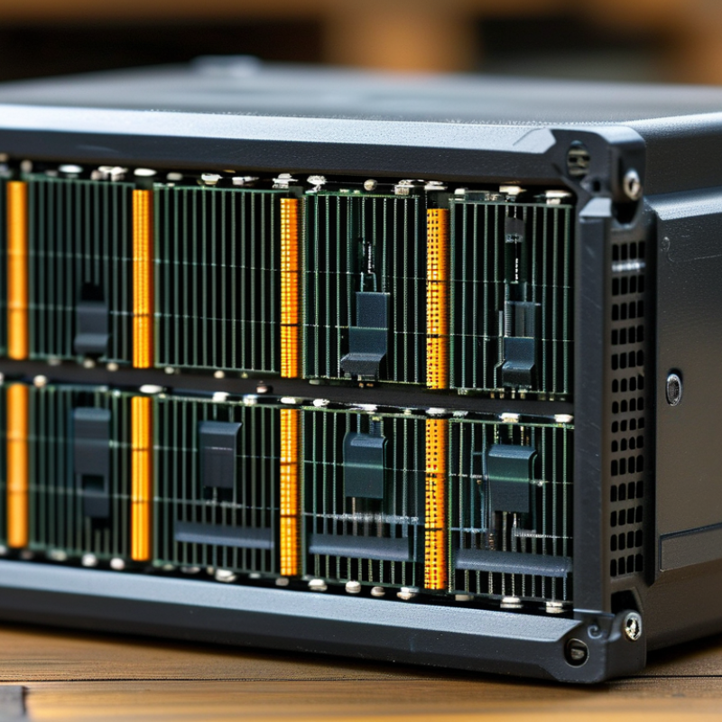
How to Choose the Right DC DC Power Module?
Define the power requirements of your system before comparing DC DC power modules. Record the input voltage range, required output voltage, and continuous load current. Include peak loads from motors, relays, wireless transmitters, or startup circuits. A module rated for average demand may fail during short surges.
Measure real operating conditions, not only values from a design sheet. For example, a 12 V system drawing 2 A needs 24 W continuously. Allow extra capacity for conversion losses, temperature, and future changes. Efficiency affects heat, especially inside a sealed enclosure. Check the module’s derating curve and calculate whether airflow is available. I have seen compact designs pass bench tests but become unstable after several hours in a warm cabinet. That mistake is easy to repeat.
Tips: Keep a clear power budget. Separate normal, peak, and standby loads. Check input ripple and output tolerance. Confirm whether isolation is necessary for safety or signal integrity. Review startup behavior, short-circuit protection, and transient response in the datasheet. Then test the module with the actual cable length and load. Real wiring can add voltage drop, noise, and unexpected heating. Leave measurable margin, but do not oversize blindly; a poorly matched module may operate inefficiently at light loads. Reliability depends on tested conditions, not attractive specifications alone.
Estimate the steady-state load, account for peak demand, and select a DC-DC power module with sufficient headroom. The recommended module rating is based on approximately 30% reserve above the estimated peak load.
A DC-DC module should match the load, not merely the voltage label. Buck converters reduce voltage, while boost converters raise it. Buck-boost designs handle changing input conditions. Isolated modules add galvanic separation through a transformer. That protection matters in industrial sensors and medical equipment. Non-isolated modules are usually smaller and more efficient. The choice depends on risk, space, and regulation requirements.
Compare input range, output accuracy, efficiency, ripple, switching frequency, and thermal limits. A module rated at 10 A may deliver less current at 85°C. Read the derating curve.
The International Energy Agency’s Electricity 2024 report expects global electricity demand to grow by about 4% in 2024 and 2025. That trend increases pressure to reduce conversion losses. A practical design should target efficiency across the normal load range, not only the headline peak. Light-load performance can be surprisingly poor.
Check transient response when motors, radios, or processors start suddenly. Measure ripple at the actual connector, using a short probe ground. Datasheet values can change with layout. This is where many selections fail.
For safety-related systems, review insulation voltage, creepage, clearance, and protection features against IEC 62368-1 requirements. Also examine short-circuit behavior and restart timing.
A cheaper module may pass bench testing but overheat inside a sealed enclosure. I would not trust efficiency claims without testing at the expected temperature, load, and airflow.
Choosing a DC DC power module requires more than comparing its headline efficiency. Check efficiency across the expected input voltage, load range, and temperature. A module rated at 95% efficiency may perform differently at light load. Measure the actual output current, ripple, and transient response in a representative circuit. Bench testing often reveals behavior that a table cannot show.
Thermal performance deserves careful attention. For example, a 24-volt input delivering 10 watts at 90% efficiency creates about 1.1 watts of heat. That heat must leave through the PCB, airflow, or a dedicated thermal path. Examine the derating curve, not only the maximum temperature rating. A crowded enclosure can raise the local temperature quickly. Small details matter.
Operating conditions should match real installation conditions. Consider input surges, continuous load, startup current, altitude, humidity, and available ventilation. Verify whether the module needs external capacitors or specific copper areas. Use temperature sensors during extended tests, especially near connectors and magnetic components. Do not trust a single successful trial. I have seen designs pass at room temperature, then fail after several hours inside a sealed enclosure. Allow safety margin, but avoid excessive oversizing, which can reduce light-load efficiency and increase cost. Datasheet limits are useful, yet application testing remains essential.
Protection features should be checked before efficiency figures. A module may tolerate a short circuit, yet fail during inrush or reverse polarity. Look for overcurrent, overvoltage, thermal shutdown, and input undervoltage protection. IEC 61000-4 testing also matters. It covers immunity against electrostatic discharge, electrical fast transients, and surge events. A 2024 report from MarketsandMarkets projects steady growth in the DC-DC converter market, driven by automation, vehicles, and communication equipment. More installations mean harsher operating conditions.
Compliance is not a logo checklist. Confirm the exact safety standard, test voltage, insulation system, creepage, and clearance. IEC 62368-1 is widely used for information and communication equipment, but the final product may require additional regional approvals. Request test reports, not only declarations. Also examine EMC limits at the intended switching frequency. A module can pass in a laboratory setup and still create noise inside a crowded enclosure. That happens.
Mechanical compatibility deserves equal attention. Measure the footprint, pin spacing, mounting height, and connector orientation. Check airflow around the case, then apply the manufacturer’s derating curve at the real ambient temperature. For example, a 10-watt rating at 25°C may not remain 10 watts inside a sealed 60°C housing. Review vibration data and soldering limits too. I have seen designs fail because the pins matched, but the heat had nowhere to escape. Datasheets are useful, but physical prototypes reveal uncomfortable details.
Selecting a reliable DC-DC power module starts with testing, not attractive specifications. A datasheet may list high efficiency, but real equipment creates different demands. Measure input voltage, output regulation, ripple, and temperature rise under realistic loads. Test the module at light load, normal load, and peak load. Short tests can hide long-term heating problems.
I once trusted a module after a clean bench test. That was a mistake. The system later produced sharp load changes, causing brief voltage drops. A programmable load can reveal this behavior. Check startup performance, recovery after a load step, and operation near the minimum input voltage. Use proper probing methods, because long oscilloscope ground leads can create false ripple readings. Test protection features carefully, including overcurrent and short-circuit responses.
Application conditions matter just as much. Confirm the required output current, isolation level, switching frequency, available airflow, and board area. A module inside a sealed enclosure needs more thermal margin than one with forced cooling. Review derating data for high ambient temperatures. Consider vibration, altitude, and continuous operating time when relevant. Pre-compliance noise testing is also valuable, although it does not replace formal certification. Leave space around hot components. Small layouts can become difficult later. A reliable choice combines measured performance with the actual electrical and mechanical conditions of the finished product.
Record input voltage range, output voltage, continuous current, peak current, and standby demand. Keep the power budget clear.
Motors, relays, transmitters, and startup circuits can create short surges. A module sized for average demand may fail during them.
It needs 24 W continuously. Add margin for conversion losses, heat, and future changes. Avoid oversizing blindly.
Efficiency losses become heat, especially inside sealed cabinets. Check derating curves and available airflow. Warm enclosures expose weak designs.
Test light, normal, and peak loads. Measure regulation, ripple, temperature rise, startup, load-step recovery, and minimum-input operation.
Yes. Cable length can add voltage drop, noise, and heating. Test with actual cables and the finished load.
Check isolation needs, overcurrent protection, short-circuit response, startup behavior, and transient response. Verify every feature carefully.
Confirm board area, switching frequency, airflow, vibration, altitude, and operating time. Leave space around hot components. Small layouts become awkward later.
Short tests can mislead. A module may pass briefly, then overheat after hours in a warm cabinet. I learned that the hard way.
Choosing the right DC/DC-Power Module begins with a clear understanding of your system’s power requirements, including input voltage range, regulated output voltage, load current, transient response, and isolation needs. Compare suitable converter types and electrical specifications to ensure the module can support both normal operation and expected power fluctuations. It is also important to examine efficiency, heat generation, thermal management, and performance across the intended temperature, humidity, and installation conditions.
Before making a final selection, verify that the module includes appropriate protection features, such as overvoltage, overcurrent, short-circuit, and thermal protection. Confirm compliance with applicable safety and electromagnetic compatibility requirements, as well as mechanical compatibility with the available space, connectors, and mounting method. A reliable choice should be supported by thorough testing, stable performance, clear technical documentation, and suitability for the application’s operating environment. Balancing electrical performance, durability, integration requirements, and long-term reliability will help ensure a safe and effective power solution.