CN Electronics
Choosing the right DC/DC-Power Controller begins with the real demands of your system, not a catalog headline. Input voltage may dip during startup. Load current may jump when a motor turns on. Heat can build inside a compact enclosure long before a bench test reveals trouble. These details shape the controller’s operating range, switching behavior, protection features, and thermal design. A useful paraphrase of power-electronics researcher Robert W. Erickson’s teaching is: “Choose the control approach to fit the converter’s operating conditions.” It is a design principle, not a direct quotation from his published work.
Start by defining the input and output voltage ranges, continuous and peak current, efficiency target, and available cooling. Then compare topology, switching frequency, feedback options, and protections such as overcurrent and undervoltage lockout. Check whether the controller supports the external MOSFETs and power components you plan to use. Also review the datasheet’s operating conditions, layout guidance, and reference designs; a promising headline specification is not a complete design.
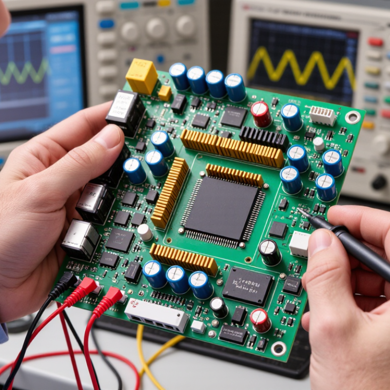
Test the actual board across expected temperatures and load changes. Watch the switch node, output ripple, and component temperatures—not just the displayed output voltage. Small layout choices matter. A long feedback trace can invite noise. A controller that looks ideal on paper may need careful compensation or a different power stage. That is worth admitting early. This guide will help you compare requirements, controller features, and validation steps before choosing a device for your application.
Define the power requirements before comparing DC-DC power controllers. Record the input voltage range, required output voltage, and continuous load current. Measure the load during startup and brief peaks, too; motors, radios, and processors can demand much more than their steady-state figures suggest. Measure it. If the source is a battery, include its voltage drop as it discharges. A controller that works at nominal input may behave differently near the battery’s lower limit.
Then examine the operating conditions. Note the ambient temperature, airflow, enclosure size, and expected duty cycle. These details affect heat dissipation and can limit usable output current. Check the controller’s efficiency across the actual input and load range, not just at one attractive test point. A spreadsheet may say the rail is safe; a sealed, sun-warmed enclosure may disagree. Leave headroom for measured peaks and component tolerances, but avoid choosing a much larger device without a reason.
Also consider electrical noise, startup sequencing, and transient response. Sensitive sensors may need a quieter supply than a switching load. Check whether the output must remain stable while the input changes quickly or the load switches suddenly. Bench testing helps expose gaps in assumptions: test at minimum and maximum input, under realistic load, and after the assembly warms up. I have seen “worst-case” estimates miss an overlooked cable drop. That estimate can be wrong. Revisit it when the actual wiring and enclosure are available.
Start by documenting the source, load, and environment. The figures below are illustrative design checks, not universal limits; confirm requirements against the application and component datasheets.
| Requirement | What to Define | Illustrative Example | Why It Matters |
|---|---|---|---|
| Input voltage range | Minimum, nominal, and maximum source voltage, including startup, dips, surges, and wiring drop. | A nominal 12 V source might require operation from 9 V to 16 V. | The controller and power stage must operate safely across the full input range, not just at nominal voltage. |
| Output voltage | Required regulated voltage and allowable tolerance at the load. | 5.0 V output with a load tolerance of ±5% corresponds to 4.75–5.25 V. | Output accuracy, feedback design, and load-side voltage drop determine whether the device receives its required voltage. |
| Load current and power | Continuous current, peak current, duty cycle, and any startup or transient demand. | A 5 V load drawing 2 A continuously requires 10 W of output power, before design margin. | Current and power ratings must cover real operating peaks as well as steady-state demand. |
| Input current and source capacity | Available source current and the expected input current at minimum input voltage. | For 10 W output at 90% efficiency from 9 V, estimated input current is about 1.23 A: 10 W ÷ (9 V × 0.90). | A source that cannot supply the required current may sag, trigger protection, or prevent startup. |
| Conversion direction and topology | Whether the output must be lower than, higher than, or both below and above the input voltage. | A 12 V input to 5 V output is a step-down application; a 5 V input to 12 V output is step-up. | The input-to-output relationship determines the suitable converter topology and its operating range. |
| Efficiency and heat | Minimum acceptable efficiency and the allowable temperature rise or heat dissipation. | At 10 W output and 90% efficiency, input power is about 11.11 W and conversion loss is about 1.11 W. | Power lost during conversion becomes heat and can affect reliability, enclosure temperature, and thermal design. |
| Ripple and transient response | Maximum permissible output ripple and voltage deviation during load changes. | A design might specify no more than 50 mV peak-to-peak ripple, measured with a defined test setup. | Ripple and load-step behavior can affect noise-sensitive circuits and must be evaluated under stated conditions. |
| Operating temperature | Minimum and maximum ambient temperatures, airflow, enclosure conditions, and nearby heat sources. | An application operating from −20°C to +70°C ambient needs components rated for the required conditions, with thermal margin. | Temperature changes component performance and reduces available power if thermal limits are reached. |
| Startup and sequencing | Required startup time, inrush-current limits, soft-start behavior, and any order-of-power requirements. | A shared source may need a controlled startup to avoid excessive input-current peaks. | Startup behavior can cause source droop, reset downstream devices, or interfere with other power rails. |
| Protection and fault conditions | Required response to input overvoltage, output overcurrent, short circuit, and overtemperature. | Confirm whether the design needs current limiting, thermal shutdown, or automatic recovery after a fault. | Protection behavior should match the system’s safety, recovery, and fault-handling requirements. |
| Electrical noise and layout | Noise limits, switching-frequency constraints, grounding approach, and space for input/output filtering. | A radio or precision-measurement circuit may need additional filtering and careful separation from switching nodes. | Switching converters can generate conducted and radiated noise; PCB layout and filtering influence the result. |
Final selection should be verified using worst-case input voltage, load, temperature, and fault conditions. Check the controller’s datasheet and evaluate the completed power stage in the intended system.
Check for overvoltage, undervoltage, overcurrent, and thermal protection. Not every controller includes all four.
Check whether the output shuts down, limits current, or restarts automatically. Recovery behavior matters.
A load may briefly draw extra current at startup. If the threshold is too low, the controller may shut down unexpectedly.
Check the full input and output ranges, not just nominal voltage. A 12-volt battery can dip during startup or face nearby switching spikes.
Poor heat removal can trigger protection. Measure temperatures in your intended layout, especially near warm components.
Compare efficiency at the loads you expect to use, not only at peak output. Small details matter.
Prototype early and record temperatures and transient response. Bench tests help, but may miss installation details.
Compare peak current, switching frequency, control-pin needs, and external components with your design. I may be overchecking, but assumptions can miss a hot spot near an inductor.
Choosing the right DC/DC-Power Controller starts with a clear understanding of the system’s input and output voltages, load requirements, operating conditions, and available space. These details help narrow the converter topology and control method to options suited to the application. Compare key ratings—including voltage range, output current, efficiency, and thermal performance—and allow for realistic operating margins rather than selecting solely by nominal values.
Next, review protection features such as overcurrent, overvoltage, and thermal shutdown, along with compatibility with the surrounding power system and components. Reliability, compliance requirements, and expected service conditions also influence the decision. Weigh these factors against trade-offs in size, cost, efficiency, and design complexity. A careful, balanced assessment helps identify a controller that can deliver stable power and dependable performance throughout the intended operating range.